The OSI model
Physical and Data Link (Layers 1 and 2)
A beginner friendly explanation of how raw signals travel over a cable and how devices on the same local network find each other.
Imagine two laptops plugged into the same box in an office wall. Before any website, app, or internet address matters, two very basic things have to happen. First, your data has to become an actual signal that can travel down the cable. Second, that signal has to reach the correct laptop and not some other device nearby.
Those are the jobs of the bottom two layers of the OSI model. Together they answer one simple question: can two devices on the same local network physically send data to each other? Everything higher up assumes the answer is already yes.
Before we start, one word you will see often. A protocol is just an agreed set of rules that two devices both follow so they can understand each other, the same way two people need a shared language to talk.
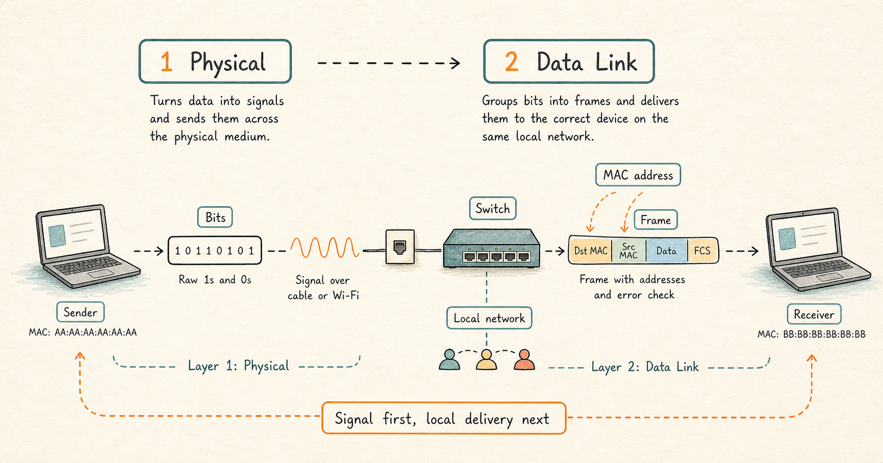
What these two layers do
- Layer 1, the Physical layer, turns your data into a signal (electricity, light, or radio waves) and sends it across some physical thing like a cable or the air. At this layer, data is just bits, meaning the individual 1s and 0s that all digital information is made of.
- Layer 2, the Data Link layer, groups those bits into bundles and makes sure each bundle reaches the correct device on the same local network.
A short way to remember it: Layer 1 asks “can a signal get across?”, and Layer 2 asks “which device is this signal for?”.
Layer 1: the Physical layer
The Physical layer is not smart. It does not understand addresses and it does not know what your data means. Its only job is to send and receive signals as fast as the connection allows.
Data travels over one of three main types of physical connection, usually called transmission media:
- Copper cable, the common wired connection, sends data as electrical signals. It is cheap and everywhere.
- Fiber optic cable sends data as pulses of light through thin glass. It is very fast, works over long distances, and is not disturbed by nearby electrical equipment.
- Wireless, such as Wi-Fi, sends data as radio waves through the air. It is convenient, but because the air is shared by everyone nearby, it is easier to disturb and slow down.
A couple of terms come up constantly when talking about a physical connection:
- Speed is how much data the connection can carry, for example 1 gigabit per second.
- Duplex describes whether a device can send and receive at the same time. Full duplex means it can do both at once, like a phone call where both people can talk and listen together. Half duplex means it has to take turns, like a walkie talkie where only one person can speak at a time.
- Negotiation is when the two connected devices automatically agree on shared settings, such as the speed and the duplex mode, without a human setting them by hand. When people say the speed and duplex were “negotiated”, they mean the two devices worked it out between themselves.
So the practical health check at Layer 1 is simple: is the connection physically plugged in, is the link active, did the two devices agree on the correct speed and duplex, and is the signal clean rather than full of errors?
Layer 2: the Data Link layer
Once bits can cross the wire, the Data Link layer makes local delivery organized and addressed.
MAC address. Every network device has a permanent hardware identity number stamped into it at the factory, called a MAC address (Media Access Control address). Think of it as a serial number for the network card. On a local network, data is delivered to a specific MAC address. Important: a MAC address only identifies a device on the same local network, not across the wider internet.
Frame. At this layer, the bits are grouped into a bundle called a frame. A frame is your data with some extra information wrapped around it, including the MAC address it came from and the MAC address it is going to. It also carries a small checksum, which is a value used to detect whether the data got damaged along the way. If the check fails, the frame is thrown away.
Switch. A switch is the device that connects all the machines on a local network. It learns which device (which MAC address) is connected to each of its ports, so it can send each frame only to the port where the destination actually is. An older, simpler device called a hub did not do this, and instead copied every message to every device, which was noisy and inefficient.
ARP. Here is a common puzzle. Programs usually know the other device by its internet address (its IP address, which belongs to Layer 3), but the Data Link layer needs to deliver frames to a MAC address. ARP (Address Resolution Protocol) is the lookup process that finds the MAC address that goes with a known IP address on the local network. In plain terms, ARP is how a device asks “who on this network has this IP address? Tell me your hardware address so I can send you the frame.”
VLAN. A VLAN (Virtual Local Area Network) is a way to split one physical switch into several separate logical networks. Two devices plugged into the same switch but placed in different VLANs cannot talk to each other directly at Layer 2, as if they were on different switches entirely. For them to communicate, their traffic has to be passed up to Layer 3 and routed.
Devices and terms you will see at these layers
- Layer 1: cables, fiber, Wi-Fi, and the network card inside your computer (often called a NIC, short for Network Interface Card).
- Layer 2: switches, MAC addresses, frames, ARP, and VLANs.
What tends to go wrong here
Because these are the lowest layers, they are the first thing to check when a network problem appears. If something here is broken, nothing above it can work, no matter how correct the rest of the setup is.
- A cable that is unplugged, loose, or damaged, or a weak Wi-Fi signal.
- A switch port that is turned off or reporting lots of errors.
- The two devices failing to agree on speed or duplex, which causes slow or dropped connections.
- Two devices that should be able to talk but were placed in different VLANs by mistake.
- An ARP problem, where a device has the wrong hardware address stored and sends frames to the wrong place.
Simple rule
Layer 1 gets the signal across the wire. Layer 2 gets it to the right device on that wire. If two machines on the same local network cannot reach each other at all, the problem almost always lives in these two layers.
Related topics
- Start here: OSI Model
- The layer above: The Network Layer (Layer 3)